

Fan Engineering From First Principles
Fan engineering first principles – a basic primer
Wherever you go you can be sure there’s a fan nearby. They must be one of the most common mechanical devices used everywhere, across the globe. Just look around you now and you’ll most likely see one nearby quietly doing its job and probably going un-noticed if it isn’t making too much noise.
To the un-initiated a fan is just a round thing with blades that pushes air. As you probably know already or will find out in this article, it’s a little bit more complicated than that.
The history with fan names
Let’s start from first principles.
The English word fan, in the context of air movement, is derived from the old English /Anglo Saxon word fann from many, many years ago. This name is not ideal if you are trying to market an air movement based website as it has another well-known meaning derived from fanatic.
The following table shows the word for fan in various languages:
| English | Fan derived from old English fann |
| French | Ventilateur derived from Latin ventilabrum |
| German | Ventilator derived from Latin ventilabrum |
| Italian | Ventilatore derived from Latin ventilabrum |
| Spanish | Ventilador derived from Latin ventilabrum |
| Polish | Wentylator derived from Latin ventilabrum |
| Chinese | 风扇 with logical symbols meaning wind and door/feather |
| Arabic | مروحة (مراوح) derived from the word for wind/breeze ر و ح |
It is quite noticeable that almost all European languages use a derivation from Latin.

What is a fan?
A good definition of a fan is a rotary mechanical device with blades and provides a continuous flow of air. The word continuous doesn’t mean it’s constantly running but when it is operating, the flow is at a steady pace. There are devices which provide pulsed flow and are not fans such as piston operated air devices and a bicycle pump is a good example.
As a general rule the rotating part of the fan is usually called the impeller and this normally has blades moving at an angle to the direction of the air flow. The force applied to the air by these blades creates a pressure, static pressure to be precise. There is often a little bit of confusion with the types of pressure so let’s see if we can clarify them here.
Under Pressure
To understand static pressure imagine a fan with an airtight chamber connected the outlet. When you run the fan the pressure in the outlet container will rise to a fixed value even though there is no air movement once it has stabilised. The pressure increase/difference in the outlet container is the static pressure. The word static is important and indicates the resulting pressure the fan creates by exerting a force to push the air without any air movement.
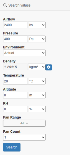
In the real world the static pressure a fan creates is normally measured while also measuring various airflows using a manometer and probe during testing. Fan testing is a specialized subject and outside the scope of this article but if you would like to know more about it we’d suggest you look at the AMCA211 or ISO13349 specifications.
There is also another pressure we need to consider called velocity pressure or sometimes dynamic pressure. This is the build-up of pressure of the air pushing on itself as it moves away from the fan. It is related to the square of the velocity of the air as it moves.
Mathematically it can be calculated using the simple equation derived from Bernoulli’s principle:
Pv = ½ ρ V²
Where:
Pv is the Velocity pressure
ρ (rho) is the density
V is the air velocity
Let’s look at a simple worked example to calculate the velocity pressure of an air stream moving at 10m/s at a standard air density of 1.225 kg/m³ * (10 m/s)²
Pv = ½ * 1.225kg/m³ * (10 m/s)² = 61.25 Pa
Now let’s look a fan which has to push air through a duct or trunking. This duct introduces a back or total pressure the fan has to work against which is the sum of both a static and dynamic pressures:
Pt = Ps + Pv
Where:
Pt is the total pressure
Ps is the static
Pv is the velocity or dynamic pressure
In fan engineering the two important pressures used are Static and Total. Often in specifications and in some cases regulations like FEI in California you need to use the right one in your calculations depending on the fan type and how it is being used.
So to recap, during testing we can evaluate how much pressure a fan can generate at varying airflows. This test data can then be used to evaluate how the fan will perform in a real world environment. This environment will have a back/total pressure that the fan has to work against. This total pressure is the sum of the static pressure applied perpendicularly to the containment of the air and the velocity pressure in the direction of the airflow.
Fan Affinity Laws
Since we got onto some simple mathematics with pressures, let’s have a quick look at the fan affinity laws. Often abbreviated to the fan laws, the word affinity just implies there is a relationship between the elements/parameters used in the calculations. Let’s look at the calculations.
Law 1: The airflow is directly proportion to the speed the fan. In a simple case if you double the speed of the fan you double the airflow.
Q2 = Q1 * (RPM2/RPM1)
Law 2: The pressure is directly proportional to the square of the speed of the fan. If you double the speed of a fan the pressure the fan needs to exert is four times as much.
P2 = P1 * (RPM2/RPM1)²
Law 3: The power is directly proportional to the cube of the speed of the fan. If you double the speed of a fan the power the fan needs to exert is eight times as much.
H2 = H1 * (RPM2/RPM1)³
Where:
Q is the air flow.
P is the pressure.
H is the fan power.
These simple natural laws are used as a basis of calculations in fan engineering. In fan selection they are very important to interpolate and extrapolate performance when the fan is being used at a different operating point to which it was tested.
Fan Efficiency
Before we leave the basic calculations for fan selection, let’s just take a quick look at fan efficiency.
A fan does not have a linear efficiency over its airflow vs pressure range. In fact all fans have a sweet spot where they are most efficient. So in the real world although a fan may be very efficient under test conditions, if it is installed in an environment where the air flow and pressure are different it may actually be very inefficient. It’s the job of the fan selection process or software to make sure this doesn’t happen.
Let’s look at the basic mathematics:
Fan Efficiency = air power out (Hair)/ power in (Hin);
The air power out can be calculated as:
Hair (Kw) = Airflow (m³/s) * Pressure (Pa)
So our efficiency calculation becomes:
Fan Efficiency = Airflow (m³/s) * Pressure (Pa)/ power in (Hin – Kw);
But which pressure do we use Static or Total? – Well we can use both to get two efficiencies:
Fan Static Efficiency = Airflow (m³/s) * Static Pressure (Pa)/ power in (Hin);
Fan Total Efficiency = Airflow (m³/s) * Total Pressure (Pa)/ power in (Hin);
So which one do we use?
Well, total efficiency is obviously the most accurate for the overall efficiency where the velocity pressure can be calculated and has a notable effect on the overall system performance. A good example here would be a housed centrifugal fan connected to ventilation ducts. In cases of free discharge or low speed applications the static efficiency is applicable and easier to assess.
We do need to look at what we’re analysing though and we haven’t defined which power in (Hin) we’re using. Generally there are four final efficiency values commonly used:
Mechanical Efficiency – Just the fan wheel or impeller where the motor and drive is not included:
Fan Static Mechanical Efficiency = Airflow (m³/s) * Static Pressure (Pa)/ shaft power in (Kw);
Fan Total Mechanical Efficiency = Airflow (m³/s) * Total Pressure (Pa)/ shaft power in (Kw);
Wire to Air Efficiency –Complete system efficiency using the air power out and electrical power in
Fan Static Electrical Efficiency = Airflow (m³/s) * Static Pressure (Pa)/electrical power in (Kw);
Fan Total Electrical Efficiency = Airflow (m³/s) * Total Pressure (Pa)/electrical power in (Kw)
We therefore have more than one efficiency to consider when putting together a fan based system. In cases where specifications and perhaps regulations are involved, it is very important to check the right efficiency value is used.
The Fan Energy Index (FEI) metric simplifies the assessment of a fan/fan systems efficiency, uses a wire to air approach and defines whether the static or total pressures are used in varying cases. The AMCA specifications 208 and 214 are a good reference and we also have an article on FEI you can read as a primer with a link in the further reading section at the bottom of this article.
Fan Sound
By definition noise is ‘unwanted sound’. Fans are naturally noisy things and it’s not surprising as they move pressure through the air which is exactly the same way sound travels. As previously mentioned different fan types can be louder or quieter than others. It is not unusual for a fan system to also have sound suppression in the form of acoustic dampers or inline silencers and often these can affect the system pressures having back pressures themselves.
Calculating fan performance at vary operating point is helped greatly by implementing the fan laws. In sound there isn’t really any natural underlying affinity law so the general rule during testing to take as many sound measurements as possible across the performance envelope of the fan. These measurements can then be used during selection to find the nearest points and interpolate between them to achieve the best estimate.
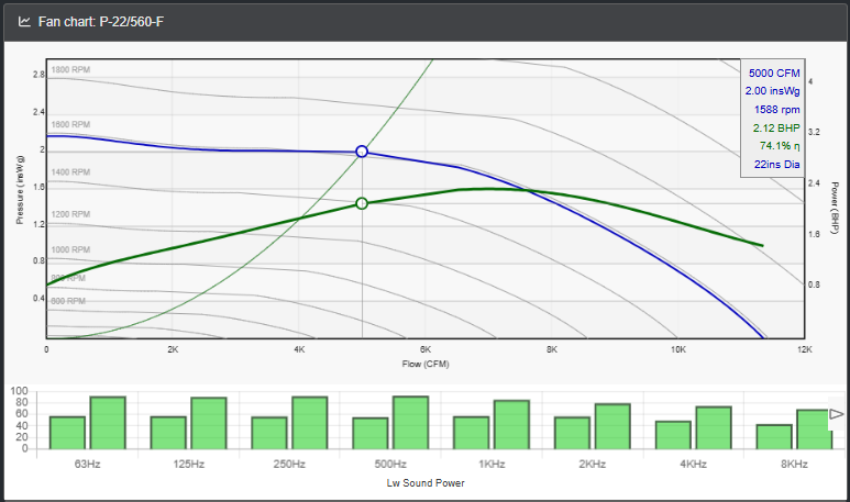
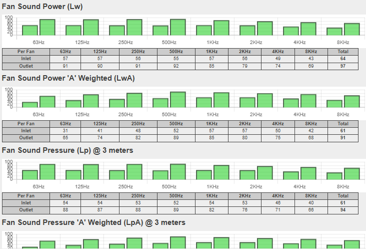
When measuring sound it is also best to take eight separate readings for sound power (Lw) across the standard octave ranges of 63Hz through to 8KHz. If accuracy is important then sometime twenty four measurements are taken with the octaves and their ‘sides’ or ‘thirds’.
The mathematics of sound prediction during fan selection can be quite complex and will be dealt with in another article. The AMCA specifications that handle fan sound are AMCA 300 for testing and AMCA 301 for calculating.

Different types of fans
So far we have taken a bit of a black box approach to fans as just air movement devices. There are many different types of fans out there and are selected depending on the type of application they are serving.
Let’s look at the 3 main types:
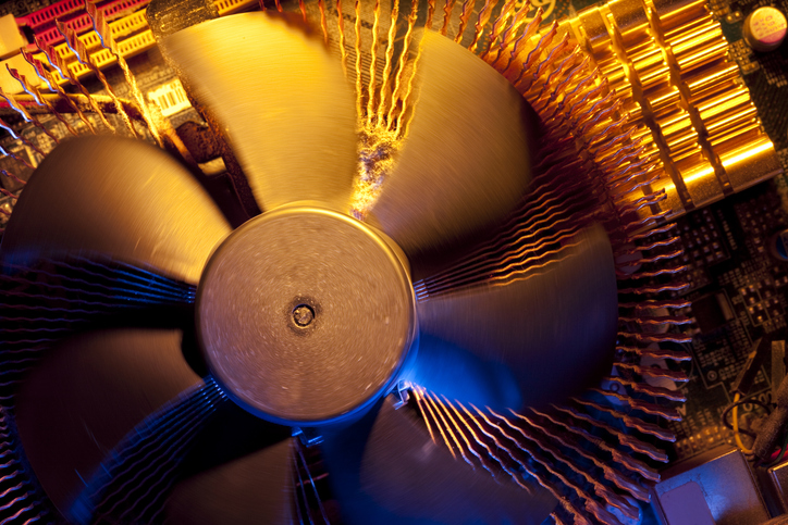
Axial Fans – In general, with axial fans the airflow is straight through the impeller from the inlet to the outlet. This is achieved by the blades providing a force on the air axially. When people think of a fan they will normally think of an axial fan and in particular a propeller fan. Generally they are better for high volume low pressure applications although there are high pressure variants.
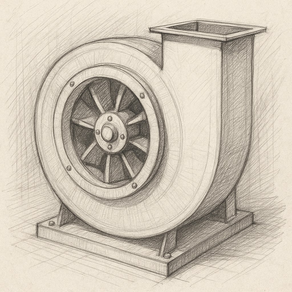
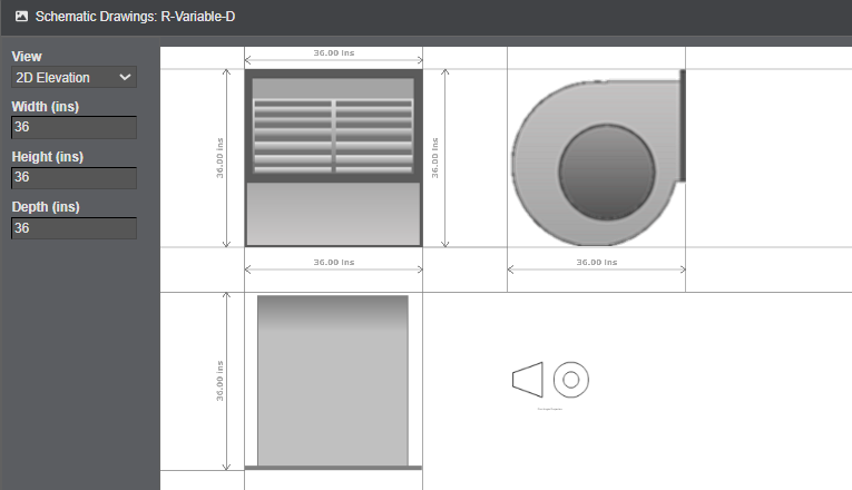
Radial/Centrifugal – Centrifugal fans look completely different from axials fans. They normally consist of a wheel, or drum, with blades on the circumference which force air out of the centre of the wheel in a centrifugal action. A good way to visualize this action is to look at a washing machine. If the drum inside had angled blades on the rim it would drive air out of the drum form the centre. So if you put a centrifugal wheel in a case with the inlet providing air to the centre of the drum and the outside of the wheel connected to the outlet – you have a centrifugal fan. Generally speaking centrifugal fans are better for applications with high pressures to work against.
Mixed Flow – A mixed flow fan uses both an axial and centrifugal action on the air from inlet to outlet. The blades force the air, which enters axially, outwards as well as forward with an angle of 30°-90°. Providing a centrifugal action on the air allows for a higher pressure demands than an axial fan.
There are many other types or sub variants such as Orifice flow, Cross flow and Outlet flow but we won’t cover those here.
Before leaving fan types, let’s quickly look at the blades used in a centrifugal fan which again have three main types
Forward Curve Blades
In a fan with forward curved blades, the blades curve forward in the same direction the wheel rotates. They provide a relatively cheap and compact solution for low to medium pressure higher volume applications, are relatively quiet and efficient when running slowly. They have been used for smaller scale HVAC applications but in more recent days their use decline in their use due to poor efficiency at higher speeds.
Backwards Curve Blades
In this case the blades face the other way, backwards to the rotation of the wheel. These can normally handle higher pressures and generally more efficient than forward curve. A fan of this type may need fewer blades and they usually have a greater radial depth. Due to the construction, they can operate at higher speed whilst still maintaining good efficiency.
Airfoil Blades
Airfoil, sometimes called Aerofoil blades are really a type of backward curved blade and perhaps could be called the posh version. Instead of the blade being solid and flat, an Airfoil blade is hollow and in a similar shape to an aeroplanes wing. Because of their design they are more efficient and can be quieter but come with a greater manufacturing cost.
There are other types or subtypes of blade, however, it would be difficult to go through them all here and not really necessary because they would be more specialised to an application.
To summarize
Fan selection is the approximation of a fans performance at a specified operating point using reference data achieved during testing.
- A fan creates a force and in turn static and velocity pressures in the air it moves and it’s good to distinguish between them when selecting fans
- There are natural relationships between the force/pressure a fan generates, the power it consumes with the speed it operates and air volume it moves. This relationship is governed by the Fan Affinity Laws.
- Fans make noise but construction type and attenuation can assist in reduce it.
There are many types and subtypes of fan but they usually fall into one of three brackets, Axial, Centrifugal or Mixed Flow.